Coastal Solar Fasteners: What Still Needs Checking After a Module Passes Salt-Mist Testing?
A photovoltaic (PV) module passing a salt-mist corrosion test does not automatically establish the corrosion suitability of every fastener and connection in a coastal solar installation. The module frame, mounting rail, brackets, bolts, washers and grounding interfaces form a connected assembly, and each interface has its own material, coating and installation requirements.
For solar asset owners, EPC quality teams and O&M managers, the important question is not simply whether the PV module passed IEC 61701 testing. It is whether the complete mounting and electrical connection arrangement has been reviewed for the actual coastal environment.
This guide provides a practical interface map, a photo-indexed acceptance checklist and a supplier evidence request list to help identify what still needs verification before project handover.
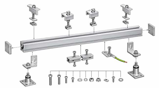
Table of Contents
- Why a Module Test Does Not Qualify the Entire Mounting System
- Identify the Five Critical PV Connection Interfaces
- Build a Coastal Solar Fastener Interface Map
- Check Corrosion Protection and Electrical Bonding Together
- Prepare a Photo-Indexed Acceptance Checklist
- What a Salt-Mist Test Report Can and Cannot Prove
- Prepare a Coastal Solar Fastener RFQ
- Frequently Asked Questions
1. Why a Module Test Does Not Qualify the Entire Mounting System
A PV module and its mounting structure are different products with different responsibilities.
A module corrosion test evaluates the tested module specimen under a defined laboratory procedure. It does not automatically verify the corrosion performance of every mounting rail, bracket, bolt, washer, grounding component or field-installed connection.
This distinction is particularly important in coastal installations, where salt deposition, humidity, wind direction, rain washing and local exposure conditions can vary considerably.
The Canadian Solar Installation Manual of Photovoltaic Modules, EN-Rev IM/GN-EN/3.1, published with a November 2025 revision date, provides a useful manufacturer-specific example.
The manual states that Canadian Solar modules have passed salt-mist corrosion resistance testing according to IEC 61701, but corrosion may still occur at the module-frame-to-bracket connection and grounding connection.
It also provides separate guidance for mounting components, material compatibility, grounding protection and coastal racking systems.
The engineering lesson is straightforward:
A module test report is evidence about the tested module, not automatic qualification of the complete PV mounting assembly.
The actual project must follow the applicable module, mounting-system and electrical-system requirements.
2. Identify the Five Critical PV Connection Interfaces
Before reviewing fastener materials, identify where the connections are located and what each connection is expected to do.
| Connection interface | Components involved | What needs verification |
|---|---|---|
| Module frame to mounting clamp | Aluminium frame, clamp and fastener | Contact geometry, material compatibility and coating condition |
| Clamp to mounting rail | Clamp, rail, bolt and nut | Fastener specification, installation requirements and joint condition |
| Mounting rail to support structure | Rail, bracket, support and bolts | Structural requirements, corrosion protection and drainage |
| Grounding connection | Module frame, grounding hardware and conductor | Electrical bonding continuity, approved hardware and corrosion protection |
| External electrical equipment | Enclosure, brackets, mounting hardware and connections | Environmental exposure, sealing arrangements and material compatibility |
These interfaces should not be treated as one generic fastening application.
For example, a mounting bolt may primarily provide mechanical retention, while a grounding connection must also satisfy electrical requirements.
The same material or coating choice cannot automatically be applied to both functions without checking the approved design.
3. Build a Coastal Solar Fastener Interface Map
A practical first step is to create a location-based interface map.
This helps EPC quality teams and asset owners connect each visible fastener to its drawing, material specification, installation record and inspection evidence.
3.1 Record the Environmental Conditions
For each connection location, record:
- Distance and orientation relative to the coastline, where relevant to the project assessment.
- Exposure to prevailing winds and salt-bearing air.
- Whether the connection is sheltered or directly exposed.
- Water accumulation, drainage and rain-washing conditions.
- Whether the connection is accessible for inspection and maintenance.
- Any known coating damage or previous corrosion observations.
Distance from the sea can be a useful project input, but it should not be treated as a universal corrosion classification.
Canadian Solar’s coastal installation guidance specifically recognizes that local conditions and wind patterns influence salt deposition. Its own distance categories are manufacturer-specific and should not be transferred to unrelated module or mounting systems.
3.2 Identify the Material Combination
The interface map should record the complete material combination, not just the bolt material.
| Component | Information to record |
|---|---|
| Module frame | Base material and surface condition |
| Mounting rail | Base material, coating or anodizing system |
| Bracket | Material, finish and contact arrangement |
| Bolt and nut | Standard, material grade, mechanical requirements and finish |
| Washer | Material, geometry and specified function |
| Grounding component | Approved construction and electrical function |
This is important because corrosion behavior can be influenced by contact between different metals and their surface coatings.
A stainless steel bolt does not independently establish that the complete connection is corrosion-compatible.
3.3 Connect Each Interface to Its Evidence
A useful record should link:
- Interface identification or drawing reference.
- Fastener part number and approved specification.
- Mating materials and coating requirements.
- Installation or inspection evidence.
- Outstanding technical questions and responsible reviewer.
The result is an interface-level record rather than a collection of unrelated product certificates.
4. Check Corrosion Protection and Electrical Bonding Together
One of the most important considerations in PV mounting is the relationship between corrosion protection and electrical bonding.
These requirements must be reviewed together.
4.1 Material Compatibility at the Contact Interface
When different metals are connected in a coastal environment, the engineering review should consider their electrochemical compatibility, surface coatings, moisture exposure and actual contact arrangement.
The Canadian Solar manual’s Annex C discusses the electrochemical potential difference between mounting, fastening or grounding components and the module frame.
It also describes insulation measures for certain configurations.
However, this is a manufacturer-specific installation approach, not a universal instruction to place insulating washers beneath every PV fastener.
The responsible system designer must determine the correct configuration for the actual module and mounting system.
4.2 Do Not Interrupt an Approved Grounding Path
Electrical bonding is not simply another corrosion-protection interface.
A grounding connection must maintain the electrical continuity required by the approved system design and applicable local electrical regulations.
Adding an insulating washer, coating or other barrier to a grounding connection without authorization could interfere with its electrical function.
The Canadian Solar manual separately describes grounding requirements, approved hardware and the responsibilities of qualified personnel.
Its grounding connection arrangement should not be copied to another manufacturer’s equipment without checking that manufacturer’s instructions and the project electrical design.
4.3 Check Coating Damage After Installation
Even an appropriately specified coating can be damaged during handling, installation or maintenance.
For coastal PV installations, the inspection should therefore include:
- Visible damage to coated mounting components.
- Scratches or exposed substrate around fastener contact areas.
- Damaged coatings around grounding interfaces.
- Water-retaining areas and blocked drainage locations.
- Any repair or maintenance records required by the approved project procedure.
Do not assume that a visually intact bolt head proves the condition of the hidden contact surfaces.
5. Prepare a Photo-Indexed Acceptance Checklist
A useful handover record should connect photographs with specific locations and technical documents.
The following is an editorial checklist for project review. It is not a replacement for an OEM installation procedure or an electrical inspection standard.
| Inspection point | Evidence to collect | Question for review |
|---|---|---|
| Module-frame connection | Close-up photograph and module installation reference | Does the installed connection follow the approved module instructions? |
| Clamp and rail connection | Photograph, component identification and drawing reference | Do the fastener and mounting components match the approved specification? |
| Rail and support connection | Photograph, material and coating records | Are the material and protection requirements documented? |
| Grounding interface | Photograph, grounding diagram and required inspection record | Is the approved electrical bonding arrangement maintained? |
| Coating condition | Photographs of visible contact areas and repair records | Are installation-related coating defects documented and addressed? |
| Water drainage | Site photographs and relevant inspection notes | Are there visible water-retaining or blocked-drainage conditions? |
| Fastener traceability | BOM, part identification and lot records | Can the installed hardware be matched to the approved procurement specification? |
Suggested Photo Identification Format
Use a consistent identification structure:
Project – Array – Row – Connection Type – Photo Number
For example:
- PV01-R03-MOUNT-001
- PV01-R03-GROUND-002
- PV01-R03-RAIL-003
These are illustrative identifiers, not actual project records.
For each photograph, retain the capture date, location, drawing reference, inspection status and reviewer.
A photograph should document an observable condition. It should not be used to claim that a hidden interface, electrical connection or mechanical property has passed inspection without the appropriate evidence.
Three Possible Review Outcomes
Each inspection item can be recorded as:
- Accepted: Required evidence is available and the responsible reviewer has accepted the item against the project criteria.
- Clarification Required: A drawing, certificate, material identification or inspection record is missing.
- Engineering Review Required: A material change, grounding modification, coating defect or unexplained deviation needs an authorized technical decision.
This makes it easier to distinguish a documentation gap from an actual technical nonconformity.
6. What a Salt-Mist Test Report Can and Cannot Prove
A salt-mist report can be useful when it is connected to a clearly defined product, specimen and acceptance requirement.
However, the test method and the product’s actual service environment are not the same thing.
The ASTM B117-26 standard information explains that salt spray testing provides a controlled corrosive environment for evaluating specimens.
Its published significance and use section also cautions that predicting natural-environment performance from stand-alone salt spray results is seldom directly correlated.
The standard does not prescribe the specimen type, exposure duration or interpretation for every product.
For solar project procurement, this means that a report stating a certain number of salt-mist hours should not automatically be interpreted as proof of a particular number of years of outdoor service.
Salt-Mist Report Review Checklist
| Report field | What the buyer should verify |
|---|---|
| Test method | Is the specified method and edition identified? |
| Test specimen | Is the tested item an actual fastener, coated component or representative test panel? |
| Material and coating | Does the specimen match the ordered product and surface system? |
| Exposure duration | Is the reported duration the contractual requirement or the actual completed test time? |
| Evaluation criteria | Are the acceptance endpoints clearly defined? |
| Laboratory and report ID | Can the report and its issuing organization be identified? |
| Production relationship | Is the tested sample traceable to the relevant product or manufacturing batch, where required? |
For a deeper explanation of test interpretation, see Flybear’s guide to what salt-spray hours can and cannot establish.
A report should support a defined procurement or quality requirement. It should not be treated as a universal service-life warranty or a substitute for system-level engineering approval.
7. Prepare a Coastal Solar Fastener RFQ
When purchasing replacement or project-specific fasteners for coastal solar installations, an incomplete request such as “stainless bolts for solar mounting” leaves too many technical questions unanswered.
A useful RFQ should include the following information.
| RFQ field | Information required |
|---|---|
| Project and application | Coastal rooftop PV, ground-mounted PV, solar tracker or another defined arrangement |
| Connection location | Module frame, clamp, rail, support bracket or grounding interface |
| Drawing and revision | Applicable assembly drawing and current revision |
| Fastener specification | Standard, dimensions, thread, material or property requirements |
| Surface finish | Required coating, passivation, anodizing or other specified surface system |
| Mating components | Frame, rail, bracket, washer, nut and grounding components |
| Environmental conditions | Coastal exposure, moisture, salt deposition and relevant maintenance conditions |
| Quantity | Required quantities by part number and project demand |
| Inspection requirements | Dimensional checks, material documents, coating inspection and any specified salt-mist tests |
| Documentation | Certificates, inspection reports, batch traceability and packing requirements |
If the proposed fastener differs from the original design, identify the deviation separately.
A supplier quotation does not constitute approval to change an OEM-specified mounting or grounding component.
How Flybear Can Support the Enquiry
Flybear provides standard fasteners, special fasteners and drawing- or sample-based custom fastener sourcing.
Depending on the agreed order specification, relevant inspection requirements can include material certificate review, dimensional inspection, hardness and tensile testing, coating-thickness inspection, appearance inspection and salt-spray testing when required.
The applicable tests, reports and acceptance criteria should be agreed before production.
You can review Flybear’s renewable-energy fastener applications and fastener quality inspection information when preparing your purchasing requirements.
8. Frequently Asked Questions
Q1. If a solar panel passes IEC 61701, are its mounting bolts also qualified?
Not automatically. The module test relates to the tested module under the applicable procedure. Mounting bolts, brackets, rails and grounding connections require their own applicable material, design and installation evidence.
Q2. Can stainless steel fasteners be used in all coastal solar installations?
No universal material choice applies to every project. Material grade, mechanical requirements, mating materials, coating systems and environmental exposure must be evaluated together under the approved design.
Q3. Should insulating washers always be installed between stainless steel bolts and aluminium rails?
No. The appropriate arrangement depends on the mounting-system design and electrical requirements. Insulation may be considered for certain corrosion-control interfaces, but must not interrupt an approved electrical bonding path.
Q4. Does a 1,000-hour salt-mist report mean that a fastener will last a certain number of years?
No. Salt-mist exposure hours cannot be directly converted into natural outdoor service years. Test reports should be evaluated against the actual specimen, test method and acceptance criteria.
Q5. What should EPC teams photograph during coastal PV installation inspection?
Useful records include module-frame connections, clamp-to-rail interfaces, rail supports, grounding arrangements, visible coating condition and drainage areas. Each photograph should have a clear location identifier and corresponding drawing or inspection reference.
Q6. What documents should be requested from a fastener supplier?
Depending on the purchase specification, request the applicable product standard, material identification or certificate, dimensional inspection results, surface-treatment records and specified test reports. Confirm the required traceability and acceptance criteria before ordering.
Conclusion: Verify the Complete Connection, Not Just the Module Test
Coastal solar fastener selection should be based on the complete installation interface rather than a single module salt-mist test result.
For project owners, EPC quality teams and O&M managers, the practical priorities are to identify the connection locations, document the material combinations, protect the approved grounding arrangement, inspect coating condition and retain traceable acceptance evidence.
A module test report is one part of the evidence package. It does not independently qualify every fastener or mounting connection in the installation.
Planning a coastal solar mounting fastener project?
Share your BOM, drawings, required standards, material specifications, surface finish and inspection requirements with Flybear.
Send your fastener enquiry to Flybear. For drawings, BOMs and specification attachments, email biz@chinaflybear.com and include the project or enquiry reference.
Follow Me!